

Adding a Mesh to an Image
1
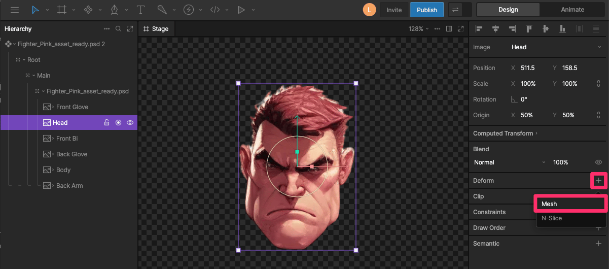
Select an image on the Stage or Hierarchy and press Enter or go to the Deform section in the Inspector.
2
Click the + button and select Mesh.
Deforming a Mesh
Enter Mesh Editing Mode by pressingV or by deselecting Edit Contour.
In mesh editing mode, moving a vertex changes the shape of any triangles connected to that vertex and deforms the pixels inside those triangles. Pixels in triangles that are not connected to the moved vertex are not affected.
Here’s a simple mesh with four vertices divided into two triangles:
Here’s a slightly more complex mesh with a center vertex, dividing the image into four triangles:
The position of these vertices can be keyed on a timeline or controlled by bones.
Contours
The contour defines the visible shape and vertex structure of the mesh. Editing the contour changes the mesh structure without deforming the image.Creating Contours
When you add a mesh to an image, Rive automatically creates a simple contour with four vertices that make two triangles. You can use this contour as a starting point or make your own.Manually Create a New Contour
Click the New Contour button to draw a new contour from scratch. This is useful when the default contour does not match the shape of the image, or when you want full control over the mesh structure.Auto-Trace a New Contour
Use Auto-Trace to quickly create a contour that follows the visible shape of an image. Adjust the settings to control the generated contour:- Detail - how closely the contour follows small details in the image.
- Concavity - how deeply the contour follows inward curves.
- Uniform - how evenly vertices are spaced along the contour.
- Alpha - the transparency threshold used to detect the image edge.
- Padding - extra space added around the traced outline.
Contour Bounds
Only the area inside the contour is rendered. Anything outside the contour is hidden. This can be useful when you want to create multiple meshes from different parts of the same image.Editing Contours
Use Edit Contour or press P to adjust the existing contour. The Mesh Pen lets you add new vertices or move existing vertices without warping the image. Click continuously to create forced edges between vertices. Press Esc between clicks to create separate vertices and let Rive automatically generate the edges between them.Forced Edges
Forced edges are edges you manually add between mesh vertices. Use forced edges when you need more control over the mesh structure, such as defining an important seam, crease, corner, or area where the mesh triangles should follow a specific path. When using the Mesh Pen, click continuously to create connected vertices with forced edges. Forced edges are shown as thicker lines in the mesh.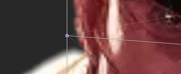
Generate
Use Generate to add more vertices to the current mesh. Click Generate multiple times to increase the mesh complexity. A more complex mesh can create smoother deformations, but it can also be harder to edit.Resetting a Contour
Use Reset to return the mesh to its default contour.Managing Meshes
Copying a Mesh
You can copy a mesh and apply it to another image.1
Select the image with the mesh you want to copy and press Cmd + C on macOS or Ctrl + C on Windows.
2
Select the image you want to apply the mesh to and press Cmd + P on macOS or Ctrl + P on Windows to paste the mesh.
Swapping Images
A mesh can continue to work when the image is changed. This is useful when multiple images share the same basic structure. The same mesh can deform each face without creating a separate mesh for every image.Removing a Mesh
After an image has a mesh, the Deform section shows options for editing or removing it.1
Select an image on the Stage or Hierarchy and press Enter or go to the Deform section in the Inspector.
2
Click the Edit Mesh or Remove Mesh button.
Mesh View Options
Mesh view options control how the mesh and image appear while editing. These options can make it easier to focus on vertices, edges, weights, or the deformed result.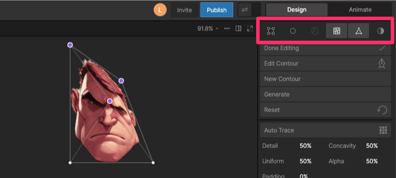
- Bounding Box Edit - show a bounding box around selected vertices so you can transform them together.
- Isolate - show only the graphic or graphics being edited.
- Show Weights - show mesh weights while editing.
- Deform - toggle between the deformed and undeformed version of the image.
- Show Triangles - show or hide the triangle edges. When disabled, only vertices are shown.
- Dim - dim the image so the mesh is easier to see.